VISUAL AND MEASURING CONTROL
VISUAL AND MEASURING CONTROL
Our visual inspection staff is certified to provide quality assurance and control services in the oil and gas, manufacturing, and energy industries. We offer a wide range of services, including:
- Plant overhaul planning:Develop and implement effective strategies for major repairs that ensure minimal downtime and maximum efficiency
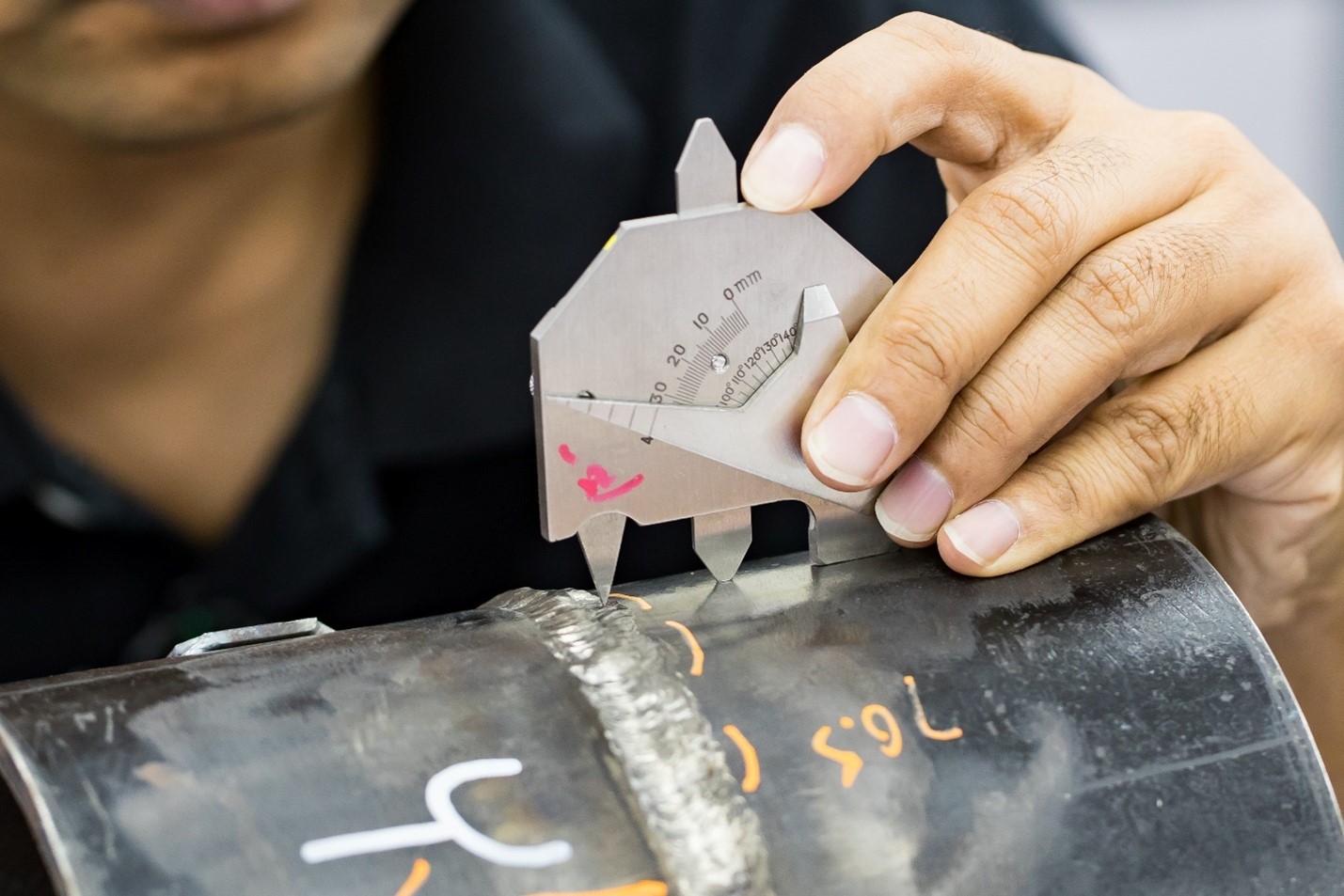
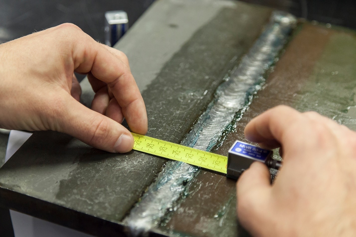
- Visual inspection of welds and dimensions:Conducting thorough inspections of welds and dimensions, ensuring their compliance with high quality and safety standards.
- Documentation quality control:Ensuring complete and accurate documentation for new and used equipment that meets all requirements and regulations.
Our specialists have the necessary knowledge and experience to perform the most difficult tasks, ensuring the high quality and reliability of the services provided.
Visual methods are often used as a complement to other non-destructive testing methods. They allow you to identify defects that may not be noticeable when using other technologies. Our specialists use a wide range of tools for visual inspection, including:
- Pressure gauges: Measuring the pressure in systems to detect deviations from the norm.
- Micrometers: High-precision measurements of dimensions and thickness.
- Calipers: Universal tools for measuring internal and external dimensions.
- Magnifying devices: Magnifying glasses and microscopes for detailed inspection of minor defects.
- Remote video equipment: Cameras and video endoscopes for checking hard-to-reach areas.
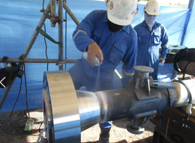
Surface preparation equipment:Tools for cleaning and preparing surfaces before performing inspections. And many other measuring equipment.
These tools ensure high accuracy and efficiency of visual inspection, which allows us to guarantee the high quality and safety of the objects being checked.
CAPILLARY CONTROL
CAPILLARY CONTROL
This method of non-destructive testing is used to detect defects and/or irregularities that destroy the surface. A low-viscosity liquid, known as a penetrant, is applied to the part and allowed to linger on the part for a certain amount of time. The excess penetrant is carefully removed and a developer is applied, which pulls the penetrant out of defects and/or irregularities due to capillary action and provides a contrasting background to improve the visibility of the readings.
The materials being tested include non-ferrous metals and ferrous metals, although ferrous metals are usually tested using a magnetic powder test to detect the subsurface layer. This method is used to detect surface defects in casting, forging, and welding and/or discontinuities such as cracks, surface porosity, leaks, fatigue cracks on operational components, and inherent manufacturing defects.
Surface preparation is crucial, so it is important to ensure that the surfaces are free of oil, grease, scale, paint, rust or other residues that may affect the quality of inspection.
MAGNETO-POWDER CONTROL
MAGNETO-POWDER CONTROL
This method is used to detect surface and subsurface defects and/or discontinuities in ferromagnetic materials. The magnetic field acts on the part, and the iron particles are magnetized while the part is being magnetized. Defects and/or discontinuities are detected when particles collect and form an indication in a magnetic field, which gives an indication of the size and location of the indication.
Magnetic powder is applied to welds, fittings, pipelines, castings, forgings, pressure vessels, machined parts, shafts, valves and structural steel.
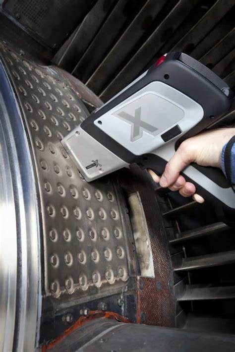
X-RAY INSPECTION (X-RAYS AND GAMMA RAYS)
 This is a non-destructive testing method that uses electromagnetic energy in the form of X-rays or gamma rays. An X-ray is a two-dimensional negative image of an object on a film that is sensitive to radiation exposure. Radiography can detect surface and subsurface defects and/or irregularities. Cobalt-60 (Co60) and iridium-192 (Ir192) are the most commonly used industrial isotopes of gamma radiation, which continuously emit gamma rays, are stored and transported in protected shielded exposure devices. An X-ray generator (also known as an X-ray tube) converts electrical energy to produce X-rays and is controlled in such a way as to stop X-rays when the equipment’s power supply is cut off. Radiography is performed on most metallic and non-metallic materials, including welds, surfacings, castings, forgings, fittings, valves and components, pipes, machined parts, pressure vessels, oil storage tanks, and structural steel. Radiography is carried out in general industrial sectors, including: energy facilities, gas production, pulp and paper mills, oil refineries and refineries, pipelines and foundries. Radiography is also widely used to determine the degree of internal and/or external corrosion/erosion in process pipelines, pressure vessels, and valves. The X-ray film provides a permanent record of the object under study. Due to the fact that the X-ray image is two-dimensional, the depth of the defect and/or discontinuity requires additional non-destructive testing, which is usually performed using ultrasound. Access to both sides of the object is required, and the processed film image is viewed and interpreted in high-intensity alternating white light. The practical thickness limit for carbon steel gamma radiography is approximately 2.5 inches for Iridium 192 (Ir-192) and 9 inches for cobalt 60 (Co-60), while the energy of the X-ray generator determines the penetration depth, which typically averages up to 1.5 inches with portable equipment. Materials with a thickness of more than 1.5 inches require stationary equipment with a high-energy X-ray generator.
ELECTRICAL CONTROL
EDDY CURRENT CONTROL
HARDNESS MEASUREMENT
- the Brinell method;
- The Rockwell method;
- The Vickers method;
 The Brinell method является статическим и регламентируется ГОСТом 9012-59. Определение твёрдости по Бринеллю производится путём вдавливания индентора в виде стального шарика соответствующего диаметра (D) в ОК при определённой нагрузке (P), приложенной к индентору строго перпендикулярно поверхности ОК. По истечении заданного времени выдержки нагрузка снимается и измеряется диаметр (d) получившегося отпечатка. Значение твёрдости по Бринеллю (HB) определяется делением нагрузки (Р) на сферическую площадь (F) отпечатка. Однако, для упрощения пользованием, таблицы твёрдости по Бринеллю составляются исходя из диаметра шарика (D), диаметра отпечатка (d) и величины нагрузки (Р). Число твёрдости обозначается цифрами и символом (например, 300 НВ).
Метод Роквелла (относится к статическим методам и определяется стандартом: ГОСТ 9013-59 (ИСО 6508-86). Для проведения этого контроля применяют в качестве индентора либо стальной шарик, либо алмазный конус, у которого угол при скруглённой вершине равен 120о.
Определение твёрдости производится по глубине погружения индентора в материал ОК. Нагрузка на индентор прикладывается последовательно в три этапа:
The Brinell method является статическим и регламентируется ГОСТом 9012-59. Определение твёрдости по Бринеллю производится путём вдавливания индентора в виде стального шарика соответствующего диаметра (D) в ОК при определённой нагрузке (P), приложенной к индентору строго перпендикулярно поверхности ОК. По истечении заданного времени выдержки нагрузка снимается и измеряется диаметр (d) получившегося отпечатка. Значение твёрдости по Бринеллю (HB) определяется делением нагрузки (Р) на сферическую площадь (F) отпечатка. Однако, для упрощения пользованием, таблицы твёрдости по Бринеллю составляются исходя из диаметра шарика (D), диаметра отпечатка (d) и величины нагрузки (Р). Число твёрдости обозначается цифрами и символом (например, 300 НВ).
Метод Роквелла (относится к статическим методам и определяется стандартом: ГОСТ 9013-59 (ИСО 6508-86). Для проведения этого контроля применяют в качестве индентора либо стальной шарик, либо алмазный конус, у которого угол при скруглённой вершине равен 120о.
Определение твёрдости производится по глубине погружения индентора в материал ОК. Нагрузка на индентор прикладывается последовательно в три этапа:
- приложение предварительной нагрузки (P0 = 10 кгс);
- приложение основной нагрузки (P), состоящей из предварительной (P0) и рабочей (Pраб) нагрузок, P = P0 + Pраб;
- снятие рабочей нагрузки, измерение глубины погружения индентора.
- способ упругого отскока;
- способ вдавливания.
 Суть этого способа (рис. 2) заключается в определении твёрдости материала ОК (2) по высоте (h2) отскока индентора (4), падающего с определённой высоты (h1), после его удара о поверхность ОК.
Приборы-склероскопы (рис. 2) для таких измерений разработаны сами́м автором метода и, в зависимости от исследуемого металла, имеют некоторые отличия. Так склероскоп типа С комплектуется индентором массой 2,5 г и высота его отскока (h2) фиксируется визуально. Склероскоп типа D имеет индентор массой 36 г, а величина отскока регистрируется электронным либо механическим устройством. Число твёрдости включает в себя цифровое значение величины твёрдости и символ (HS) с указанием шкалы, по которой произведён отсчёт – например, 95 HSD.
Суть этого способа (рис. 2) заключается в определении твёрдости материала ОК (2) по высоте (h2) отскока индентора (4), падающего с определённой высоты (h1), после его удара о поверхность ОК.
Приборы-склероскопы (рис. 2) для таких измерений разработаны сами́м автором метода и, в зависимости от исследуемого металла, имеют некоторые отличия. Так склероскоп типа С комплектуется индентором массой 2,5 г и высота его отскока (h2) фиксируется визуально. Склероскоп типа D имеет индентор массой 36 г, а величина отскока регистрируется электронным либо механическим устройством. Число твёрдости включает в себя цифровое значение величины твёрдости и символ (HS) с указанием шкалы, по которой произведён отсчёт – например, 95 HSD.
LEAK DETECTION
THERMAL IMAGING INSPECTION
- During construction quality control – detection of hidden cracks in walls, errors in the installation of windows and doors, weak insulation of walls, roofs, floors, etc., insufficient tightness of joints in walls.
- Detection of overheating of electrical wiring, aggregates, mechanisms and prevention of emergencies.
- Leakage of heat carriers in heating mains, leakage of refrigerant in air conditioning systems, leakage of hot or cold water.
- Checking the insulation of the walls, searching for weak points in the insulation.
- Using a thermal imager, you can find wires and pipes hidden in the walls.
- And many other ways to use the thermal imager in both domestic and industrial premises.
- - defects in thermal insulation between the lining and the pipe trunk; • tracing of heating mains, specifying the locations and sizes of expansion joints; • defects in thermal insulation in underground pipelines (destruction, wetting); - defects in the pipe trunk (cracks, leaky concreting seams, areas of porous concrete); -defects in pipe lining (cracks, falling bricks, loose mounting openings); • defects in the thermal insulation of furnaces, pipelines, etc. • identification of pipeline rupture sites
- gas leakages; • damage to pipeline insulation; • defects in tank walls; • detection of leaks and oil spill sites; • determination of the liquid level in the tank.
- The required temperature difference should be at least 10-15C degrees. The greater the temperature difference, the more accurate the research data.
- The room must not be exposed to direct or reflected sunlight for at least 12 hours, otherwise the data will be inaccurate.

METAL MAGNETIC MEMORY METHOD
CONTACTLESS MAGNETOMETRIC DIAGNOSTICS
VIBRATION CONTROL
SPECTRAL ANALYSIS
SPECTRAL ANALYSIS
 Spectral methods are widely used in various industries for quality control of raw materials and finished products, monitoring of technological processes. They allow you to quickly obtain information about the composition and properties of various materials, identify defects, and prevent defects.
Spectral analysis is performed on ferrous and non-ferrous metal materials, including welds, surfacings, castings, forgings, valves and components, pipes, fittings, machined parts, pressure vessels, structural steel, and components,
Spectral methods are widely used to control the composition and properties of metals and alloys. They allow you to determine the content of alloying elements, impurities, and also detect various defects, which is important for ensuring the quality of metal products.
The main purpose of spectral analysis is:
- Steel grade confirmation;
- selection of analogues of steels and alloys;
- updating of technical documentation;
The key advantage of the method is that the analyzed material does not need to be destroyed directly during the spectral analysis.
ACOUSTIC EMISSION CONTROL
ACOUSTIC EMISSION CONTROL
It is based on the emission and registration of stress waves during rapid local restructuring of the material structure. Defects that occur and develop in the material during operation cause a concentration of deformations. If, during loading, the local strain (overvoltage) caused by the presence of a defect exceeds the threshold level for emission, acoustic emission occurs. The higher the deformation caused by the defect, the higher the emission level and the lower the load level at which it appears. The total energy of the emission is a measure of the risk of a defect. A defect located in a more stressed area of the object causes a higher stress concentration and higher emission than a similar defect located in a less stressed area. From the point of view of the structural integrity of the object, a defect located in a more loaded area is more dangerous than a similar defect in a less loaded area. Acoustic emission tests allow us to establish this difference.
The classical sources of AE are the processes of plastic deformation and fracture. The rapid movement (growth) of the AE source causes the appearance of stress waves that propagate in the material structure and reach the piezoelectric transformer. The electrical emission signals received as a result of the voltage wave conversion by the sensor are amplified, recorded by the equipment and subjected to further processing and interpretation.
Modern systems measure both individual parameters of an AE signal: amplitude, duration, energy, oscillations, time of arrival, time of rise, and other parameters related to its frequency characteristics, as well as the shape of the digitized signal. The analysis of the set of parameters of the sequence of AE signals makes it possible to determine the location of the source, its type and degree of danger. A detailed analysis of the shape/spectrum of the digitized signal is used to clarify the type of source and propagation characteristics of the signal.
 Since the source of acoustic emission energy is the field of elastic stresses in the material, AE control is usually carried out by loading the controlled object. This can be a pre-launch verification check, periodic monitoring during operation, or monitoring. Acoustic emission differs from most non-destructive testing (NDE) methods in three key aspects.
- The signal source is the material itself, not an external source, i.e. the method is passive (and not active, like most other control methods). This, in turn, leads to the fact that:
- Unlike other methods, AE detects developing, i.e. the most dangerous defects
- This method is remote, it does not require scanning the surface of the object to search for local defects, but only the correct placement of sensors on the surface of the object to locate the AE source
The opportunities associated with the remote use of the method offer great advantages over other control methods that require, for example, removing insulating shells, freeing control objects from internal contents, or scanning large surfaces. Due to the difference in their capabilities from traditional control methods, in practice it turns out to be very useful to combine AE with other methods. The use of the AE method significantly reduces the time of diagnostic work and saves money spent on their implementation and decommissioning of equipment.